Boiler Feed Pump Cavitation Diagnostics & NPSHa Verification
An advanced engineering treatise on identifying acoustic cavitation signatures, calculating true NPSH margins under saturated deaerator boiling conditions, analyzing transient depressurization, and designing anti-flashing suction piping.
Key Anti-Cavitation Takeaways
- The Flashing Threshold: Saturated 130°C feedwater flashes explosively with a local pressure drop of only 0.15 bar (2.2 psi).
- Transient Trip Risk: Sudden steam supply loss creates rapid deaerator pressure collapse, flashing downcomer water before it reaches the impeller.
- Suction Velocity Limit: Keep suction piping fluid velocity between 0.8 and 1.5 m/s (2.5 to 5.0 ft/s) per Hydraulic Institute HI 9.6.1.
- Acoustic FFT Signature: Cavitation emits high-frequency broadband noise (5 kHz to 20 kHz), distinct from 1X unbalance.
Test Your Pump Suction Velocity and NPSH Margin Live
Calculate pipe velocity, velocity head, and verify NPSHa compliance against manufacturer 3% head drop curves.
Handbook Engineering Contents
- The Physics of High-Temperature Feedwater Cavitation
- Acoustic Cavitation Diagnostics vs Mechanical Imbalance (FFT Telemetry)
- Transient Deaerator Depressurization Following Turbine Trips
- Piping Geometry Rules: Eccentric Reducers, Velocities & Nozzle Straight Runs
- The NPSH Margin Criteria per Hydraulic Institute (HI 9.6.1)
- Plant Field Troubleshooting Checklist & Remedial Engineering
- Frequently Asked Questions (FAQ)
1. The Physics of High-Temperature Feedwater Cavitation
Cavitation in boiler feed pump applications differs fundamentally from cold-water municipal pumping. Because feedwater drawn from deaerator vessels exists at saturation temperatures ranging from 105°C to 160°C (221°F to 320°F), even a minuscule localized pressure depression of 0.1 bar triggers violent vapor flashing.
When saturated feedwater enters the low-pressure suction eye of the first-stage impeller, fluid acceleration produces a local drop in static pressure per Bernoulli's principle:
If $P_{eye} \le P_{vapor}(T)$, micro-cavities of water vapor form spontaneously. As the rotating blades push these vapor cavities into the higher pressure diffuser channels, the surrounding liquid crushes the bubbles in microseconds.
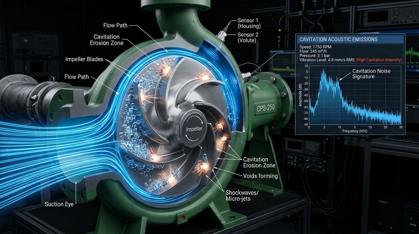
The bubble collapse is asymmetrical: a high-velocity micro-jet forms and punctures the bubble center at velocities between 1,000 and 1,500 m/s, striking the metallic blade surface. The impact produces localized water-hammer pressures between 2,000 and 10,000 bar (29,000 to 145,000 psi), eroding even hardened 13% chrome (CA6NM) stainless steels through microscopic fatigue spalling.
2. Acoustic Cavitation Diagnostics vs Mechanical Imbalance (FFT Telemetry)
In industrial plant operations, maintenance teams frequently confuse acoustic cavitation with mechanical unbalance, bent shafts, or misalignment. Accurate vibration telemetry prevents unnecessary and expensive machine disassemblies.
| Diagnostic Indicator | Acoustic Cavitation Flashing | Mechanical Shaft Imbalance |
|---|---|---|
| Audible Noise | Rattling gravel, frying bacon, or loud crackling | Low-frequency continuous rotational hum |
| Primary Vibration FFT Frequencies | Broadband high frequency (5 kHz – 20 kHz) | Discrete 1X running shaft frequency (29.5 Hz @ 1770 RPM) |
| Sensor Placement Sensitivity | Highest on pump suction nozzle and first-stage volute | Highest on radial bearing housings (NDE and DE) |
| Response to Throttling Discharge Valve | Noise drops immediately as flow decreases toward BEP | Vibration amplitude remains unchanged across flow rates |
As illustrated in Figure 3.1, piezoceramic acoustic emission sensors mounted on the suction housing capture broad continuous energy bands between 5 kHz and 20 kHz. When high-frequency root-mean-square vibration exceeds 4.5 mm/s RMS, cavitation bubble implosion is actively eroding blade surfaces.
3. Transient Deaerator Depressurization Following Turbine Trips
The most dangerous operational threat to a boiler feed pump is not normal steady-state operation, but sudden steam supply disruptions. In combined-cycle and thermal power plants, deaerators receive heating steam from turbine extraction bleeds.
When a turbine trip occurs, extraction non-return valves slam shut within 200 milliseconds. Steam supply to the deaerator drops to zero instantly. Meanwhile, the large volume of cold condensate continues entering the vessel dome.
Consequently, the deaerator vessel pressure ($P_{deaerator}$) collapses exponentially within seconds. However, the thousands of kilograms of hot water in the downcomer suction pipe cannot cool immediately due to high thermal inertia.
The hot water inside the downcomer pipe suddenly finds itself in a superheated state relative to the decayed vessel pressure. The water column boils explosively inside the suction pipe, creating massive steam vapor pockets that starve the pump of liquid, causing violent cavitation, hydraulic shockwaves, and instant seizure of interstage wear rings.
4. Piping Geometry Rules: Eccentric Reducers, Velocities & Nozzle Straight Runs
Correct physical layout of suction piping is mandatory to maintain fluid laminar stability and prevent vapor trapping. The following four rules must be enforced during plant engineering review:
- Suction Velocity Restriction (0.8 to 1.5 m/s): Never allow suction flow velocity to exceed 1.5 m/s (5.0 ft/s) per Hydraulic Institute standard HI 9.6.1. Higher velocities create steep Darcy-Weisbach head loss, devouring precious NPSHa.
- Mandatory Flat-on-Top Eccentric Reducers: When reducing pipe size down to the pump suction nozzle, always specify an eccentric reducer installed flat-on-top. A concentric reducer creates an inverted pocket that traps steam bubbles, which feed into the impeller eye in destructive slugs.
- Straight Run Upstream of Suction Flange: Provide at least 5 to 10 straight pipe diameters without elbows, valves, or strainers directly upstream of the pump suction nozzle to eliminate pre-rotational swirl and asymmetric impeller blade loading.
- Cruciform Anti-Vortex Baffles in Storage Vessel: Weld a cruciform baffle directly over the vessel drain nozzle to prevent whirlpool vortex formation from pulling steam bubbles into the downcomer.
5. The NPSH Margin Criteria per Hydraulic Institute (HI 9.6.1)
Pump manufacturers publish NPSHr curves based on the 3% head drop criterion (NPSH3). This is the condition where cavitation has already grown so severe that pump head has degraded by 3%. In high-energy boiler feed service, operating near NPSH3 causes rapid blade destruction within months.
Per Hydraulic Institute standard ANSI/HI 9.6.1, boiler feed pumps require a substantial safety margin ratio:
Absolute Head Margin: ΔH = NPSHa - NPSHr ≥ +1.5 m to +2.5 m (5.0 to 8.2 ft)
Ensuring this margin guarantees that micro-bubble inception occurs safely upstream of the critical blade leading edge, eliminating cavitation erosion over the 40,000-hour design life of the machine.
6. Plant Field Troubleshooting Checklist & Remedial Engineering
Field Diagnostic Protocol for Suspected Cavitation:
A partially fouled temporary or permanent suction strainer can easily drop 0.5 to 1.0 bar (5 to 10 m of head), destroying NPSHa. Inspect and clean mesh baskets immediately.
Check calibrated magnetic level gauges against DCS transmitters. A low liquid level reduces static head ($Z_{suction}$) below the minimum allowable design elevation.
Ensure the ARV bypass opens properly during low load startup. If the valve fails to open, internal fluid dissipation induces thermal cavitation within 30 seconds.
Ensure downcomer piping is thoroughly thermally insulated. Damaged cladding or missing insulation causes uncooled hot spots that accelerate flashing transients.
7. Frequently Asked Questions (FAQ)
What causes severe cavitation in boiler feed pumps even when the deaerator is elevated?
The most frequent cause is transient deaerator pressure decay following sudden turbine trips or boiler firing cutbacks. When steam supply to the deaerator stops abruptly, vessel dome pressure collapses faster than the bulk hot water can cool. High-temperature water in the downcomer flashes explosively into vapor bubbles prior to entering the impeller eye, causing severe flashing cavitation despite static elevation.
What is the recommended suction line velocity for boiler feed pumps per Hydraulic Institute standards?
Per Hydraulic Institute (HI 9.6.1) and API 610 guidelines, boiler feed pump suction piping velocity must be strictly restricted to 0.8 to 1.5 m/s (2.5 to 5.0 ft/s). Keeping velocity low minimizes Darcy-Weisbach friction head losses and dampens acoustic turbulence upstream of the first-stage impeller eye.
Why must eccentric reducers on pump suction lines always be installed flat-on-top?
Installing an eccentric reducer with the flat side on top (flat-on-top orientation) prevents vapor and non-condensable gases from pocketing at the top of the horizontal pipe run. A concentric reducer creates an inverted hump where trapped steam bubbles accumulate and feed into the impeller in catastrophic slugs.
How do you differentiate between acoustic cavitation and mechanical unbalance using vibration analysis?
Acoustic cavitation emits high-frequency broad-band crackling noise (resembling gravel rattling inside the pump casing), typically detected in the high-frequency vibration spectrum between 5 kHz and 20 kHz with high crest factors. In contrast, mechanical unbalance manifests as discrete 1X running frequency peaks on accelerometer FFT spectra.
What is the minimum required NPSH margin ratio for high-energy boiler feed pumps?
Per Hydraulic Institute (ANSI/HI 9.6.1) for high-energy pumps (head per stage >200 m or power >225 kW), the NPSH margin ratio (NPSHa / NPSHr) should be at least 1.30 to 1.80, or a minimum static head margin of +1.5 to +2.5 meters, to prevent 40,000-hour impeller cavitation erosion.
Explore Related Engineering Guides
Deepen your understanding of feed tank volume sizing principles and API 610 casing architecture comparisons.