Boiler Feed Tank & Deaerator Storage Sizing Principles
A comprehensive engineering guide on determining effective liquid retention time, gross shell capacity, anti-vortex baffling, surge buffers, and elevation head per ASME Section VIII and Hydraulic Institute standards.
Core Storage Sizing Principles
- 10–20 Minute MCR Rule: Storage capacity must provide between 10 (packaged firetube) and 20 (utility watertube) minutes of full-load steaming buffer.
- 60% Usable Volume Factor: Sizing requires $V_{gross} = V_{effective} / 0.60$ to accommodate vapor disengagement and lower anti-vortex buffers.
- Anti-Vortex Nozzle Submergence: Maintain a minimum liquid column of $1.5 \times D_{nozzle}$ above downcomers to prevent vapor drawing into pump suction.
- Static Elevation Driving Head: Because suction water is at saturation boiling, vessel elevation is the only defense against pump cavitation.
Size Your Feedwater Storage & NPSHa Instantly
Use our live calculation suite to evaluate tank retention time, elevation head, and suction piping friction.
Handbook Engineering Contents
- The Operational Role of Boiler Feed Storage Vessels
- The 10–20 Minute MCR Retention Rule: Thermodynamic Derivations
- Gross vs. Usable Effective Capacity: Geometry and Zonal Allocation
- Anti-Vortex Baffling & Minimum Downcomer Submergence
- Elevation Head & Saturated Suction Dynamics
- Worked Industrial Calculation: 50 Ton/Hour Watertube Deaerator Skid
- Frequently Asked Questions (FAQ)
1. The Operational Role of Boiler Feed Storage Vessels
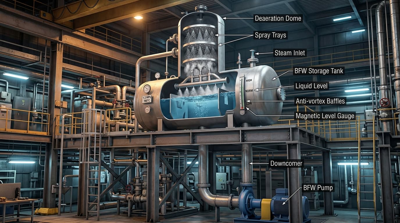
In steam plant engineering, the boiler feed tank (also termed hotwell, surge vessel, or deaerator storage tank) performs three irreplaceable thermodynamic missions simultaneously. First, it acts as a hydraulic surge damper between erratic condensate return flows and continuous boiler feedwater demand.
Second, when configured as a thermal deaerator, it exposes water to low-pressure steam via spray nozzles and perforated cascade trays. This heats incoming water to saturation boiling temperature, reducing dissolved oxygen to <7 ppb and eliminating free carbon dioxide to prevent severe localized pitting in economizer and boiler tubes.
Third, the vessel provides a physical elevated head reservoir that creates positive static suction pressure ($Z_{suction}$) at the boiler feed pump suction nozzles, ensuring continuous compliance with Net Positive Suction Head requirements.
2. The 10–20 Minute MCR Retention Rule: Thermodynamic Derivations
How much water storage is truly necessary? Sizing a tank purely on physical footprint risks plant trips, whereas extreme over-sizing increases capital steel cost, structural foundation weight, and standing radiation thermal losses.
Global engineering standards (including ASME, British BS 845, and Spirax Sarco industrial codes) establish that effective storage capacity must guarantee between 10 and 20 minutes of continuous steaming at Maximum Continuous Rating (MCR):
Where:
- V_effective: Usable water drawdown volume ($m^3$ or gallons).
- M_steam: Boiler steaming rate at 100% MCR (kg/h or lb/h).
- t_retention: Required retention time in minutes (10 to 20 min).
- ρ_water: Water density at operating saturation temperature (typically 930–955 kg/m³).
| Boiler & Process Architecture | Recommended Retention | Primary Operational Rationale |
|---|---|---|
| Packaged Firetube Boilers | 10 – 12 Minutes | Large internal water inventory in shell buffers short feed supply interruptions. |
| Industrial Watertube Boilers | 15 – 18 Minutes | Low water drum capacity requires rapid makeup during batch process steaming swings. |
| Utility Power & Cogeneration | 18 – 25 Minutes | Absorbs full turbine trip transients, extraction steam cuts, and deaerator pressure decays. |
| Biomass & Waste Heat (HRSG) | 20 – 30 Minutes | Compensates for sluggish furnace response and long condensate return loops. |
3. Gross vs. Usable Effective Capacity: Geometry and Zonal Allocation
A frequent design error made by junior piping engineers is assuming that total internal vessel volume equals usable water capacity. In reality, only 55% to 65% of the cylindrical shell internal volume can ever be utilized for pump supply:
An industrial horizontal storage vessel is divided into three distinct vertical zones:
- Top Vapor Disengagement Cushion (20%–25%): The space above high-water alarm level. This zone must remain empty of liquid to allow flashed steam disengagement, prevent water carryover into steam vents, and provide surge room for sudden slug returns of cold condensate.
- Usable Effective Operating Drawdown (55%–60%): The active liquid volume between the Normal Water Level (NWL) and the Low Water Cutoff (LWCO). This is the true hydraulic storage that protects the plant during makeup water disruptions.
- Bottom Anti-Vortex Heel (15%–20%): The liquid layer beneath the low-level trip nozzle. This water is hydraulically dead storage necessary to maintain positive liquid submergence over the pump downcomer nozzles.
4. Anti-Vortex Baffling & Minimum Downcomer Submergence
When fluid is extracted at high velocity through a bottom nozzle, a free-surface vortex (swirling whirlpool) forms naturally above the drain opening. In a boiler feed tank, this vortex pulls low-pressure vapor and non-condensable gases directly into the pump downcomer pipe.
Ingestion of even 1% to 2% vapor by volume into a multistage centrifugal pump destroys hydraulic head generation, causes severe shaft vibration, and triggers catastrophic dry running of balance drums and mechanical seals.
To eliminate vortex formation, two mandatory design rules must be implemented:
- Minimum Submergence Rule: The liquid height above the top of the downcomer nozzle ($S$) at lowest operating level must satisfy: $S \ge 1.5 \times D_{downcomer}$.
- Cruciform Anti-Vortex Baffles: A cross-shaped baffle assembly (minimum height $1.0 \times D$, width $2.5 \times D$) must be welded directly inside the vessel shell over the nozzle opening to destroy rotational fluid momentum.
5. Elevation Head & Saturated Suction Dynamics
Because water inside a deaerator exists at its boiling saturation point, liquid surface pressure equals saturation vapor pressure ($P_{suction} = P_{vapor}$). In the Net Positive Suction Head equation, the pressure terms cancel completely:
∴ NPSHa = Z_suction - h_friction
Therefore, the vertical distance from the pump impeller shaft axis to the low water level of the deaerator ($Z_{suction}$) is the sole source of positive head. For an API 610 BB3 multistage pump requiring 3.5 m NPSHr, a minimum static height of 6.0 to 8.0 meters is standard engineering practice to guarantee an adequate safety cushion against pipe friction and transient deaerator pressure drops.
6. Worked Industrial Calculation: 50 Ton/Hour Watertube Deaerator Skid
Plant Design Input Parameters:
- Boiler Maximum Continuous Rating (MCR): 50,000 kg/h (50 t/h)
- Continuous Surface Blowdown: 4.0%
- Target Retention Time: 15 minutes of usable drawdown at MCR
- Operating Deaerator Temperature: 125°C (ρ = 939 kg/m³)
- Selected Shell Length-to-Diameter Ratio: L/D = 3.5
Step-by-Step Sizing Derivation:
7. Frequently Asked Questions (FAQ)
What is the standard retention time for an industrial boiler feed tank or deaerator?
Industrial engineering standards specify 10 to 20 minutes of effective water storage calculated at the boiler Maximum Continuous Rating (MCR). Packaged firetube boilers operating with steady steam demand can operate reliably on a 10–12 minute buffer. Conversely, rapid-cycling industrial watertube boilers, biomass plants, and power utility installations require 15 to 20 minutes of reserve storage to absorb condensate return delays and feedwater surges.
Why must gross tank volume be sized approximately 40% to 50% larger than effective volume?
Effective volume accounts strictly for the usable drawdown liquid between the high-water alarm level and the low-water trip level. Gross internal shell volume is typically sized as V_gross = V_effective / 0.60 to preserve a 20% top vapor disengagement cushion for steam sparging and flashing, plus a 20% submerged buffer at the bottom to maintain minimum liquid submergence over the downcomer nozzle and prevent vortex cavitation.
What minimum liquid submergence is required over the suction downcomer nozzle?
To avoid free-surface vortex formation that ingests steam and non-condensable gas bubbles into the downcomer, minimum liquid submergence above the nozzle must equal at least 1.5 times the downcomer inside diameter (S ≥ 1.5 × D_downcomer). Additionally, cross-type cruciform anti-vortex baffles should be welded directly over the downcomer inlet nozzle.
How does deaerator storage elevation directly govern feed pump NPSHa?
Because water in a thermal deaerator is kept at boiling saturation temperature, its surface liquid pressure equals its vapor pressure. In the NPSHa equation, (P_suction - P_vapor) / (ρ × g) cancels to zero. The vertical liquid column elevation above the pump impeller centerline is the sole driving force ensuring NPSHa exceeds the pump NPSHr.
What occurs inside the storage tank during a sudden plant steam turbine trip?
When a turbine trips, extraction steam supply to the deaerator stops abruptly. Vessel dome pressure collapses faster than the bulk hot water can cool. The water in the upper liquid layer flashes explosively into steam, reducing downcomer static pressure and inducing severe flashing cavitation at the pump suction eye unless an adequate vertical head margin exists.
Explore Related Engineering Guides
Review our mathematical derivations for boiler feed pump head calculation and pump cavitation prevention.